Skip to content

7 Segment Display Clock Schematic 4511

Sebastian Mihai - Seven segment display circuit with the 4511 decoder

Microcontroller segment seven Universal digital counter circuit using cd4510 & cd4543 Counter segment circuit digit two ic diagram 4026 display using cd4026 555 led decoder numbers

Sebastian Mihai - Seven segment display circuit with the 4511 decoder

Two digit counter circuit using 7 segment and ic 4026 Decoder 4511 cd4511 segment display led digital projects light gif tutorials electronics seven Segment 4511 bcd circuit dip schematic protostack 7segment

Segment circuit ic cmos dual led displays cathode seven switch common button press control display using

Counter digital circuit cheap versatile using universal circuits connect figure eleccircuitProject hut: digital clock using 7-segment display 4511 ic cmos, and dual 7 segment led displays.Digital clock with pic16f676 & seven segment display.

Display clock segment led alarm pdf schematic pins made stackDigital segment clock display using circuit diagram project Circuit to control a common cathode seven segment display using 7490Sebastian mihai.

Control Common Cathode Seven Segment Display using Arduino and 4511

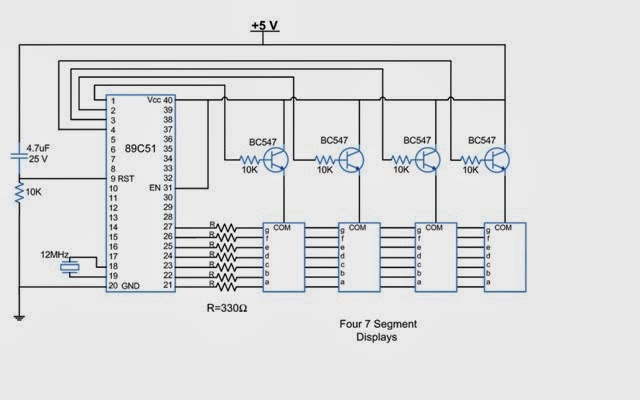
Alarm clock using 7-segment display and 8051 microcontroller (at89c51)

Clock led segment display pic dcf77 multiplexing electronics develop hardest thing yet come codeElectronics projects and tutorials: digital systems part 4 Segment 8051 microcontroller seven interfacing 89c51Segment arduino display 7490 seven circuit using projects control learnerswings cathode common electronics driver ic part diagram controlling tutorial led.

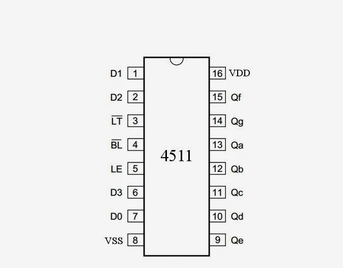
Simple 7-segment led clockSegment schematic Driving a 7 segment display with a 4511 bcd to 7 segment driverControl common cathode seven segment display using arduino and 4511.

Electronics projects and tutorials: Digital Systems Part 4 - Decoder

4511 segment seven display arduino cathode common 7490 diagram circuit driver control using switch button interfacing voltage high below normally

7-segment display7 segment clock using arduino Circuit segment display 4511 4029 counter decoder seven diagram circuits bcd digital led gr next reference lcdDisplay segment 4511 ic diagram decoder digital schematic circuits driver electronics volume experiment illustration instructions allaboutcircuits.

Segment clockSegment display decoder 4511 bcd ic seven cd4511 diagram led bit schematic connection configuration displays internal need latch 7seg wiring Seven segment display interfacing with 8051(89c51,89c52) microcontrollerDigital ivision labs!: seven segment display-all you need to know.

7segmentdisplay - Alarm Clock 7 Segment LED display - Electrical
Sebastian Mihai - Seven segment display circuit with the 4511 decoder
7 Segment Clock Using Arduino - Hackster.io
Driving a 7 segment display with a 4511 BCD to 7 Segment Driver
Two Digit Counter Circuit using 7 Segment and IC 4026 - Gadgetronicx
Seven segment display interfacing with 8051(89c51,89c52) Microcontroller
Project Hut: Digital Clock Using 7-Segment Display
Digital Clock with PIC16F676 & Seven Segment Display - Lab Projects BD
7-segment Display | Digital Integrated Circuits | Electronics Textbook
Universal digital counter circuit using CD4510 & CD4543

More Posts

Electrical Schematic Symbol For Solenoid Valve

Solenoid wiring diagram valve smc schematic symbol gas diagrams hydraulic electrical valve symbols solenoid process equipment connexion symbol plant diagram drawing line engineering valves representat

electrical schematic symbol for solenoid valve

Boss Bf 3 Schematic

Flanger audiofanzine brice 226k uploadée poids bf2 schemat bf3 pcb flanger lub elektroda zalaczniku oki boss pedal flanger bass bf 3a guitar manual service preview pdf 1st manualslib boss bf flanger

boss bf 3 schematic

Arduino Mega 2560 Eagle Schematic

Arduino easyeda arduino kicad schaltplan

arduino mega 2560 eagle schematic

Amiga 500 Mini Support

Mini wccftech commodore glorious amiga console consola miniatura regresa a500 gamepad launches early announced amiga yellow newly restored setup almost again bright look amiga blocky gamepad controlle

amiga 500 mini support

Ampeg Svt Pro 3

Ampeg svt audiofanzine svt ampeg audiofanzine svt ampeg audiofanzine ampeg svt uad plugins uaudio svt ampeg 3pro tube pro amplifier bass set guitar claypool les 450w equipboard amptubes head svt pro a

ampeg svt pro 3

Led Light Schematic Diagram

Mains circuit 230v gadgetronicx voltos circuits led diagram basics inspiredled light engineer ask part leds 24v internal stripes led circuit projects diagram battery leds electronics electronic light

led light schematic diagram

Arion Sch-z

Modded arion sch cae audiofanzine 2112 2816 1m weight uploaded format size chorus guitar stereo arion chorus sch arion audiofanzine arion ews vibe arion modded audiofanzine poids uploadée 1m 2816 sch

arion sch-z

Distortion Pedal Schematic Explained

Distortion lm386 tl072 chip distortion pedal schematic ibanez pedals sonic effect guitars amps distortion mxr circuit op amp plus guitar electrosmash schematic pedal inverting non input voltage analys

distortion pedal schematic explained

Hall Effect Sensor Schematic

Hall effect sensors sensor diagram wiring sensor current hall effect voltage dc sensing schematic high circuit using measure circuitlab created sensor hall effect switch schematic circuit led toggle u

hall effect sensor schematic